NavKar Systems
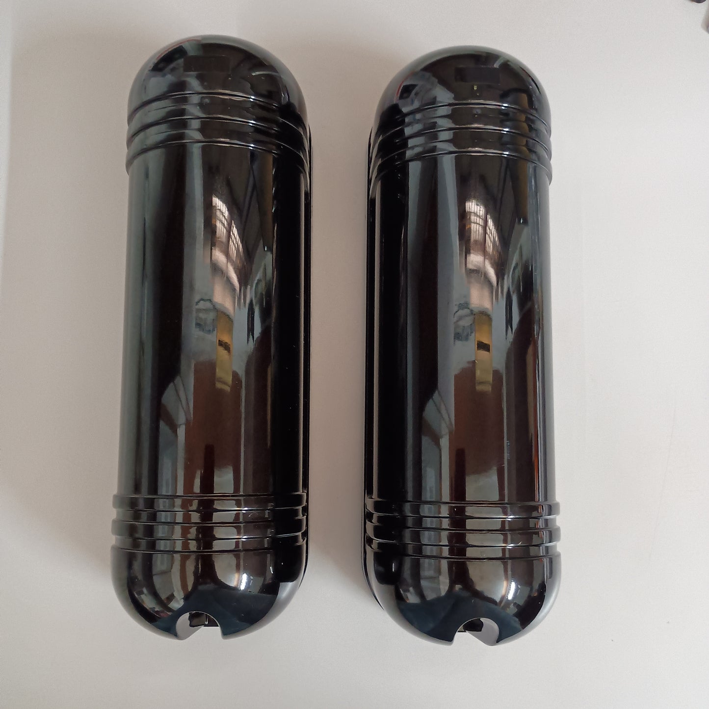
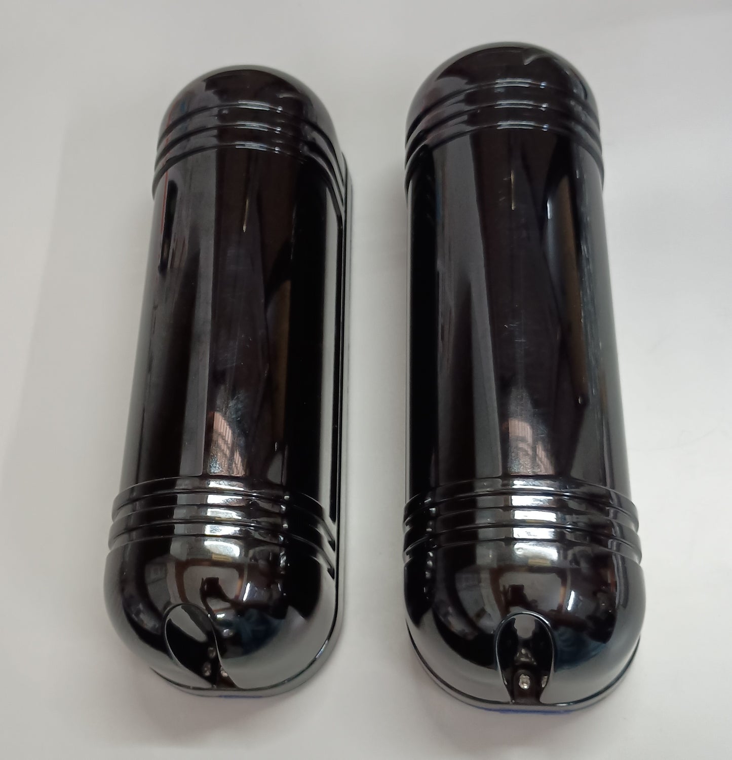
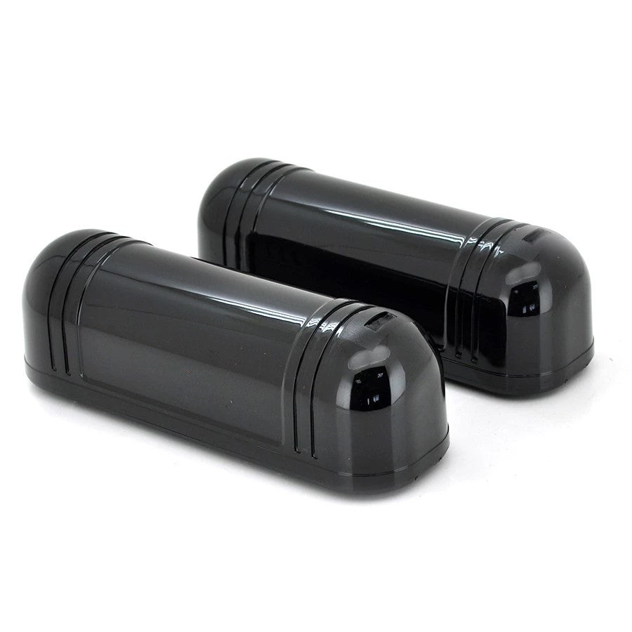
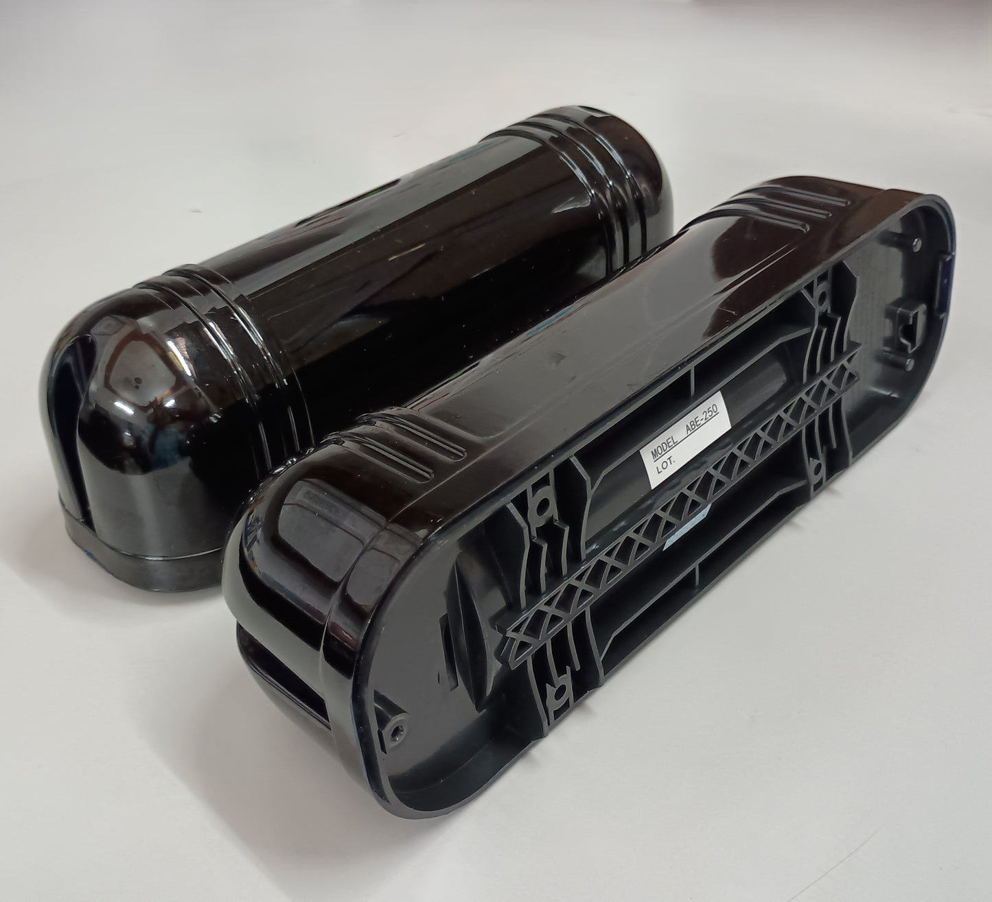
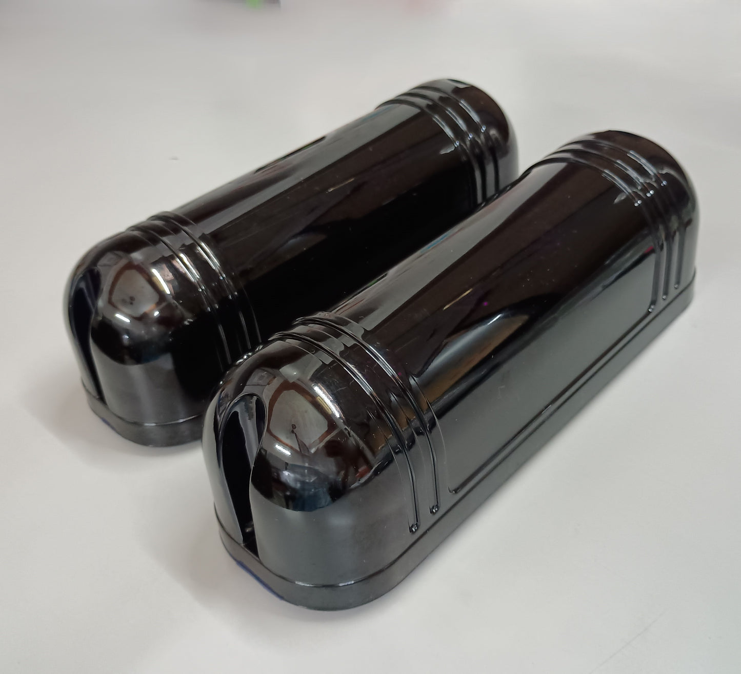
ABT-250 Weatherproof Triple Beam Alarm Photoelectric Infrared Led Detector Security System, Home Security Alarm Infrared Detector Sensor 3 Beam Sensor
ABT-250 Weatherproof Triple Beam Alarm Photoelectric Infrared Led Detector Security System, Home Security Alarm Infrared Detector Sensor 3 Beam Sensor
Couldn't load pickup availability
Brand: NAVKAR SYSTEMS
Color: Black
Model No: ABT-250
Features:
- Detector pair: No. of Beams- 3, Distance between beams- The Beams can be mounted up to 150 meters apart
- Time adjustment for pass blocking (have influence on detection sensitivity- User selectable digital processing programmable time
- Alarm Output - YES –Contact NO/NC Type
- WORKING VOLTAGE - DC 10.5-30V DC, Working temperature- - 30° + 50° C
- Weight- 0.6 kg (without adapter), RF-Detector pair With Power: Detector With Power model With additional RF transmitter module in receiver beam , for connectivity with security systems or wireless alarm/hooter- 315/433 mhz ,pls. confirm for available stock before ordering this variant, Clock Adjusment- Support time is automatically updated
PRINCIPLE:
The 3 Beam Active Infrared Photoelectric Detector is a long-range perimeter security sensor designed to protect open areas, boundary walls, gates, driveways, industrial premises, warehouses and other restricted zones. It uses three active infrared beams between a transmitter and receiver to create an invisible detection barrier. When all three beams are simultaneously interrupted, the receiver activates the alarm output. This simultaneous-beam detection helps provide reliable perimeter intrusion detection.
- 3-Beam Active Infrared Technology – Uses three infrared beams to create an invisible security barrier.
- Long-Range Perimeter Protection – Outdoor detection range available up to 250m, depending on model.
- Indoor Range up to 750m – The corresponding indoor range is up to 750m for the 250m model.
- Simultaneous 3-Beam Detection – Designed to trigger when the three infrared beams are interrupted together.
- Adjustable Response Time – Response/interruption time can be adjusted from approximately 50–700 ms, allowing the system to be configured according to the protected area's requirements.
- Beam Alignment Adjustment – Horizontal adjustment of approximately ±90° and vertical adjustment of approximately ±10° helps simplify transmitter-receiver alignment.
- LED Signal-Level Indicators – Multiple level indicators help installers check and fine-tune beam alignment.
- Alarm Relay Output – Provides NO/NC relay contacts for connection to compatible alarm panels and security systems.
- Tamper Protection – Tamper output can indicate unauthorized opening/removal of the detector cover.
- Wall or Pole Mounting – Suitable for installation on walls or poles.
- Outdoor-Oriented Construction – The technical documentation specifies operation across approximately -25°C to +55°C with humidity up to 95%, depending on the exact version.
Specifications:
- Product Type: 3 Beam Active Infrared Photoelectric Detector
- Detection Technology: Infrared Photoelectric
- Number of Beams: 3
- Detection Method: Simultaneous interruption of 3 infrared beams
- Outdoor Range: 50m / 100m / 150m / 200m / 250m
- Indoor Range: 150m / 300m / 450m / 600m / 750m
- Optical Source: Infrared digital pulse beam
- Response Time: 50–700 ms adjustable
- Power Supply: DC 12–24V / AC 11–18V
- Horizontal Adjustment : ±90°
- Vertical Adjustment: ±10°
- Operating Temperature:-25°C to +55°C
- Humidity: Up to 95% RH
- Mounting: Wall or Pole
- Housing Material: ABS/PC resin, depending on version
Package List:
- 1 × Infrared Transmitter Unit
- 1 × Infrared Receiver Unit
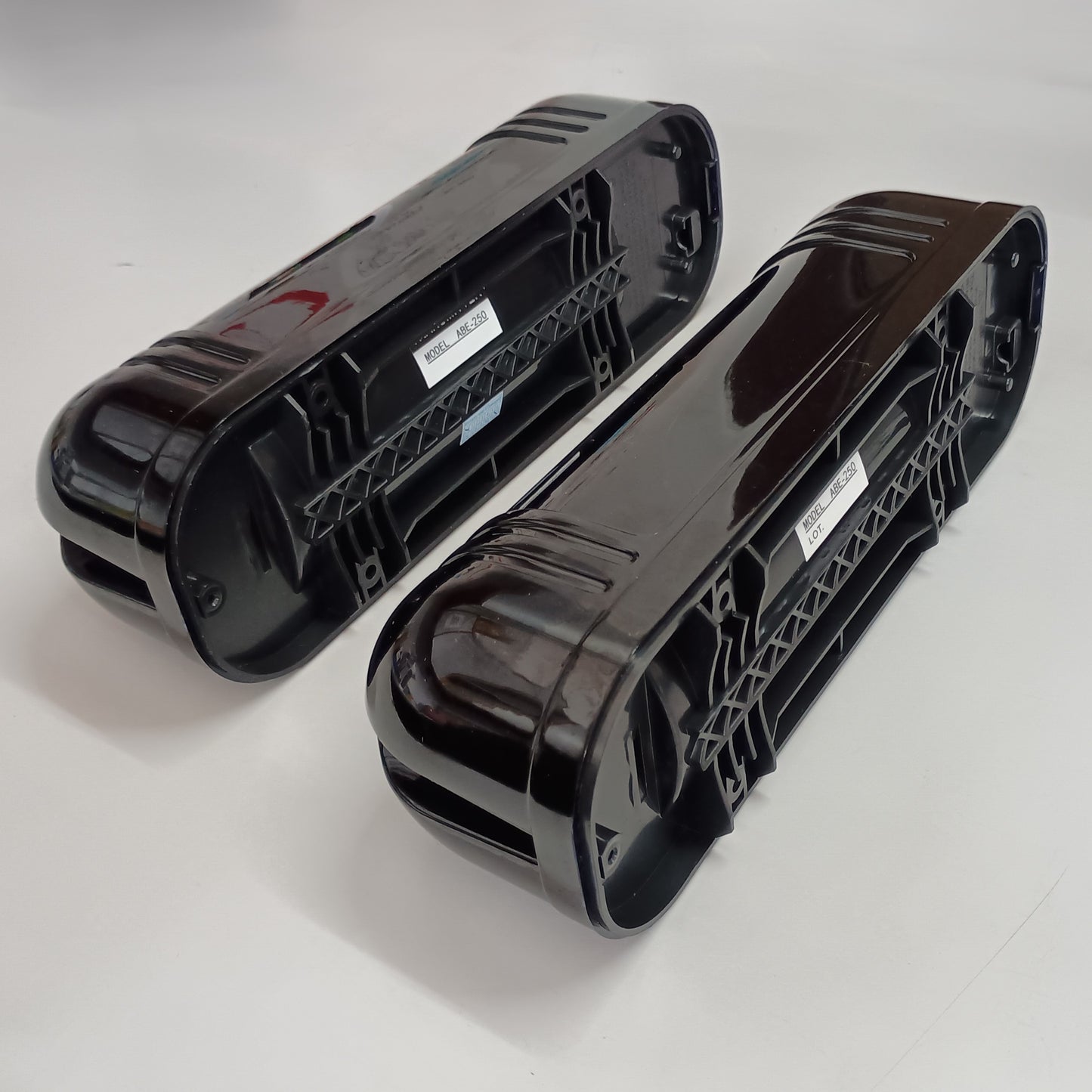
- Mounting Brackets / Base Plates for installing the transmitter and receiver
- Mounting Screws & Hardware
- Wiring Terminals integrated into the transmitter and receiver
- Protective Housing / Covers for the detector units
- Installation Guide / User Manual
Applications:
- Boundary wall perimeter security
- Factory and industrial premises
- Warehouses and storage yards
- Residential compounds and villas
- Large houses and farmhouses
- Parking areas
- Restricted access zones
- Solar/PV installations
- Commercial properties
How It Works
In simple terms: Transmitter → 3 Invisible IR Beams → Receiver → Alarm Output
This makes it particularly useful for creating an invisible perimeter protection line across boundary walls, entrances, passages and open areas.
System Components
Transmitter: Sends the three modulated infrared beams toward the receiver.
Receiver: Receives the three infrared beams and provides the alarm relay output when the protected beams are interrupted.
Product Overview
Product Description
The NAVKAR SYSTEMS ABT-250 is a 3-Beam Active Infrared Photoelectric Detector designed for long-range perimeter security and intrusion detection. It uses a transmitter and receiver pair to create three invisible infrared beams across a protected area. When the configured beams are interrupted, the receiver activates the alarm relay output.
Main Purpose
The ABT-250 is designed to create an invisible security barrier around boundary walls, gates, driveways, warehouses, factories, industrial premises, parking areas, residential compounds, and other restricted zones.
Key Benefits
- Provides 3-beam infrared perimeter protection.
- Supports long-distance transmitter-to-receiver installation, depending on the selected configuration.
- Helps reduce unwanted detection by using multiple infrared beams.
- Offers adjustable response/interruption time for different site requirements.
- Provides NO/NC alarm relay output for connection to compatible security systems.
- Supports wall or pole mounting.
- Includes beam alignment adjustment for easier installation and setup.
Important Features
- 3 active infrared beams
- Simultaneous beam interruption detection
- Adjustable response time of approximately 50–700 ms
- NO/NC relay alarm output
- Horizontal adjustment: approximately ±90°
- Vertical adjustment: approximately ±10°
- Operating voltage: DC 10.5–30V
- Suitable for outdoor-oriented perimeter security applications
- Optional RF transmitter variant available for compatible wireless alarm/hooter systems, subject to stock availability.
Product Specifications
Model: ABT-250
Product Type: 3-Beam Active Infrared Photoelectric Detector
Brand: NAVKAR SYSTEMS
Power Supply: DC 10.5–30V
Communication: Wired / Alarm Relay Output
Operating Range: Up to 150 meters between transmitter and receiver, as specified for the supplied ABT-250 configuration
Material: Outdoor protective ABS/PC-type housing
Dimensions: Not specified in the provided product information
Number of Beams: 3
Detection Method: Simultaneous interruption of 3 infrared beams
Response Time: Approximately 50–700 ms, adjustable
Alarm Output: NO/NC relay contact
Horizontal Adjustment: Approximately ±90°
Vertical Adjustment: Approximately ±10°
Operating Temperature: -30°C to +50°C
Mounting: Wall or pole mounting
Weight: Approximately 0.6 kg without adapter
Optical Source: Infrared digital pulse beam
RF Variant: Optional 315/433 MHz RF transmitter version, subject to stock availability
Applications
- Boundary wall and perimeter security
- Factory and industrial premises
- Warehouses and storage yards
- Residential compounds and villas
- Large houses and farmhouses
- Gates and entrances
- Parking areas
- Restricted access zones
- Commercial properties
- Solar and PV installations
- Driveways and open passages
- Security-sensitive outdoor areas
Suitable For
Perimeter Security: Suitable for protecting boundary walls, fences, gates, driveways, and open perimeters.
Industrial & Commercial Sites: Suitable for factories, warehouses, storage yards, commercial buildings, and restricted industrial areas.
Residential Properties: Suitable for villas, farmhouses, large residential compounds, and private properties requiring perimeter intrusion detection.
Large Open Areas: Suitable for parking areas, solar/PV installations, passages, and other areas where an invisible detection barrier is required.
Outdoor Installations: Suitable for outdoor-oriented security installations where the transmitter and receiver can be securely aligned and mounted.
Security Systems Integration: Suitable for connection to compatible alarm panels, security systems, and other equipment through its NO/NC relay output.
Not Suitable For
Very Short-Distance Detection: Not necessary for applications where only a very short detection distance is required.
Indoor Access Control: Not designed to function as a standalone door access-control or attendance device.
Areas With Obstructed Beam Paths: Not suitable where walls, trees, vehicles, equipment, or other objects continuously block the infrared beam path.
Poorly Aligned Installations: Not suitable for installations where the transmitter and receiver cannot be securely positioned and accurately aligned.
Applications Requiring Wireless Connectivity as Standard: The standard configuration uses wired power and relay connections; wireless connectivity requires the optional RF variant and should be confirmed for availability.
Unsuitable Environmental Conditions: Avoid installation where the detector is exposed to conditions beyond its specified operating temperature or where environmental factors prevent reliable beam transmission.
Package Contents
- ABT-250 3-Beam Active Infrared Photoelectric Detector Set
- Mounting Hardware / Bracket Set (as shown in the package)
- 3 Beam Active Infrared Photoelectric Detector Installation Guide
Installation
- Select the Installation Location
Select a firm and stable mounting surface for both the transmitter and receiver. Install the two units facing each other with a clear line of sight. Do not install where trees, vegetation, walls, equipment, or other objects can obstruct the infrared beams. Avoid direct sunlight or strong light falling directly on the receiver. - Maintain the Required Detection Distance
Position the transmitter and receiver within the applicable detection range. The manual lists the outdoor range variants as 50 m, 100 m, 150 m, 200 m and 250 m, with corresponding indoor ranges up to 150 m, 300 m, 450 m, 600 m and 750 m. For the ABT-250 configuration, use the applicable 250 m outdoor / 750 m indoor specification indicated in the manual. - Remove the Detector Cover
Loosen the cover-locking screw and carefully remove the cover from the transmitter and receiver units. - Mark the Mounting Holes
Place the supplied installation template/stencil at the selected mounting position. Mark the mounting-hole positions on the wall or mounting surface and drill the required holes. - Route the Cable
Pass the power and signal cables through the designated wiring hole in the detector housing before fixing the detector body. - Fix the Detector Body
Position the transmitter and receiver bodies on their respective mounting locations and securely fasten them using suitable screws and mounting hardware. Both units should be firmly mounted so they do not move after alignment. - Pole/Bracket Installation
For pole mounting, route the cable through the bracket, remove the detector cover, fasten the base plate to the fixed bracket, and secure the detector body to the bracket. Back-to-back installation can also be performed where required. - Connect the Wiring
Connect the power, alarm and tamper connections according to the terminal diagram provided in the manual. Do not apply voltage or current exceeding the detector's specified electrical ratings. - Align the Transmitter and Receiver
Apply power and perform beam alignment using the built-in viewing/alignment system. Adjust the horizontal and vertical adjustment mechanisms until the transmitter and receiver beams are correctly aligned and the receiver indicates strong signal reception. The manual specifies approximately ±90° horizontal and ±10° vertical adjustment. - Adjust the Beam Response Time
Set the receiver's response time according to the required detection condition. The manual provides selectable settings corresponding to different movement speeds, from high-speed movement to slow walking. - Perform a Physical Test
After alignment, test the protected area by interrupting the beams and verify that the receiver changes to the alarm condition and activates the connected alarm output. - Close the Detector Covers
After successful wiring, alignment, response-time adjustment and testing, securely reinstall the transmitter and receiver covers. Ensure the covers are properly closed to protect the internal components.
Wiring
The ABT-250 wiring should be completed according to the terminal diagrams shown in the supplied user manual. Switch OFF the power before making any connections.
Power Connection
Transmitter:
Connect the DC power supply to the transmitter's Power Supply terminals 1 and 2.
Receiver:
Connect the same-rated DC power supply to the receiver's Power Supply terminals 1 and 2.
The manual specifies a DC 24V power supply for the 3-beam detector. The supplied wiring diagram also shows the power connection to both the transmitter and receiver.
Alarm Output
The receiver provides a relay alarm output for connection to an alarm panel or compatible security system.
COM: Common relay terminal
NC: Normally Closed relay contact
NO: Normally Open relay contact
Connect the alarm panel or external security device to the required COM + NC or COM + NO terminals according to the alarm system's required operating logic.
Tamper Connection
The manual also provides tamper-proof switch terminals. These can be connected to the tamper input of a compatible alarm/security panel to detect unauthorized opening or removal of the detector cover.
Transmitter Terminals
- Terminals 1–2: Power supply
- Terminals 3–4: Spare terminals as indicated in the manual
- Tamper terminals: Use the terminals marked for the tamper-proof switch
Receiver Terminals
- Terminals 1–2: Power supply
- Alarm relay: COM / NC / NO
- Tamper terminals: Terminals marked for the tamper-proof switch
Transmitter–Receiver Wiring Distance
The manual provides the following maximum cable distances between transmitter and receiver:
Wiring Distance Between Transmitter and Receiver
- 0.5 mm² wire (Ø0.8): Up to 300 m at DC 12V and 600 m at DC 24V.
- 0.75 mm² wire (Ø1.0): Up to 400 m at DC 12V and 800 m at DC 24V.
- 1.25 mm² wire (Ø1.2): Up to 700 m at DC 12V and 1400 m at DC 24V.
- 2.0 mm² wire (Ø1.6): Up to 1000 m at DC 12V and 2000 m at DC 24V.
Programming
The ABT-250 does not require software-based programming. Configuration is performed manually using the beam alignment adjustments and receiver response-time adjustment provided on the detector.
1. Beam Alignment
- Power ON the transmitter and receiver after completing the wiring.
- Remove the receiver cover.
- Use the viewfinder to check the infrared beam position.
- Adjust the horizontal angle adjustment knob until the beam is correctly positioned.
- Adjust the vertical angle adjustment screw to fine-tune the beam position.
- Check the receiver's signal-level indicators. A stronger signal indication confirms better beam alignment.
- Complete the alignment for reliable detection before replacing the cover.
2. Response Time Adjustment
Adjust the receiver's beam response time according to the movement speed that needs to be detected.
- Setting 1 – High Speed: For very fast movement.
- Setting 2 – Fast Running: Approximately 6.9 m/s.
- Setting 3 – Fast Walking: Approximately 1.2 m/s.
- Setting 4 – Normal Walking: Approximately 0.7 m/s.
- Setting 5 – Slow Walking: Approximately 0.4 m/s.
The manual recommends setting the response time to be less than the time taken by an intruder to cross the protected beam area.
3. Final Testing
- After alignment and response-time adjustment, close the detector cover.
- Walk through the protected beam area at the intended detection speed.
- Confirm that the receiver changes to the alarm condition when the three beams are interrupted simultaneously.
- Verify that the connected alarm panel or security system receives the alarm signal.
Troubleshooting
Problem: The transmitter LED does not light up
Solution: Check the power wiring, power supply voltage, and terminal connections. Make sure the transmitter is receiving the required power.
Problem: The receiver LED does not light up
Solution: Check the receiver power wiring and confirm that the correct power supply is reaching the receiver.
Problem: Alarm does not activate when the beam is blocked
Solution: Check the transmitter and receiver alignment. Remove any object reflecting or obstructing the beam, make sure all three beams are being detected correctly, and check the response-time setting.
Problem: Alarm activates continuously
Solution: Re-align the transmitter and receiver. Check for obstacles, vegetation, dust, or other objects between the units. Also check that the detector covers are properly fitted.
Problem: Alarm activates intermittently
Solution: Check the power supply and wiring. Remove obstacles from the beam path, improve the transmitter-receiver alignment, and ensure the installation is stable. Check for moving objects such as vegetation that may interrupt the beams.
Problem: Weak beam signal
Solution: Adjust the horizontal and vertical alignment of the detector. Use the receiver's signal-level indicators to obtain the strongest possible signal.
Problem: Detector does not detect movement correctly
Solution: Check the beam response-time setting and select the appropriate setting for the expected movement speed. Also verify that the three beams are correctly aligned.
Problem: Alarm output does not operate
Solution: Check the wiring and relay connections, particularly the COM, NO and NC terminals. Confirm that the connected alarm system is compatible with the relay output.
Problem: Beam alignment cannot be completed
Solution: Check that the transmitter and receiver are securely mounted and facing each other. Remove obstructions and avoid direct sunlight or strong light entering the receiver. Re-adjust the horizontal and vertical alignment.
Problem: Detector becomes unstable in bad weather
Solution: Check the detector covers and installation stability. Remove moisture, dirt, vegetation, or other obstructions affecting the beam path. Recheck beam alignment after severe weather conditions.
Common Problems
1. No power to the transmitter or receiver – Check the power supply, polarity, wiring connections, and terminal connections.
2. False alarms – Check beam alignment and remove vegetation, moving objects, dust, or other obstructions from the beam path.
3. Beams are not aligned correctly – Adjust the horizontal and vertical alignment until the receiver indicates a strong and stable signal.
4. Detector does not detect an intruder – Check that all three infrared beams are functioning and that the response-time setting is appropriate for the expected movement speed.
5. Alarm output does not activate – Check the receiver's COM, NO, and NC relay connections and verify the connected alarm system.
6. Intermittent alarm – Check for unstable mounting, loose wiring, environmental obstructions, or an unstable power supply.
7. Weak infrared signal – Re-align the transmitter and receiver and ensure there are no obstructions or strong light sources affecting the receiver.
8. Detector performance changes in outdoor conditions – Check the detector covers, beam path, mounting stability, and alignment after rain, strong wind, or other environmental changes.
FAQs
Q: What is the NAVKAR SYSTEMS ABT-250?
A: The ABT-250 is a 3-Beam Active Infrared Photoelectric Detector designed for perimeter security and intrusion detection.
Q: How many infrared beams does the ABT-250 use?
A: It uses three active infrared beams between the transmitter and receiver.
Q: What happens when the beams are interrupted?
A: When the configured three beams are interrupted simultaneously, the receiver activates its alarm relay output.
Q: What is the maximum distance between the transmitter and receiver?
A: The supplied specifications indicate that the beams can be installed up to 150 meters apart for the stated configuration. Range can vary by model/version.
Q: Can the ABT-250 be used outdoors?
A: Yes. It is designed for outdoor-oriented perimeter security applications such as boundary walls, gates, warehouses, factories, and open areas.
Q: What type of alarm output does it provide?
A: The receiver provides NO/NC relay contacts for connection to compatible alarm panels and security systems.
Q: Can the response time be adjusted?
A: Yes. The response/detection time can be adjusted according to the movement speed and requirements of the protected area.
Q: Can the detector be mounted on a wall or pole?
A: Yes. The detector supports wall or pole mounting.
Q: Does the ABT-250 require an internet or Wi-Fi connection?
A: No. The standard detector operates using wired power and relay connections and does not require Wi-Fi or internet connectivity.
Q: Is an RF version available?
A: An optional RF detector-pair version with an additional RF transmitter module is available for compatible wireless security systems or alarm/hooter applications. Availability should be confirmed before ordering.
Q: What should I do if the detector gives false alarms?
A: Check the transmitter-receiver alignment, remove objects or vegetation from the beam path, check the power supply, and verify the response-time setting.
Q: What should I do if the detector does not detect movement?
A: Check the beam alignment, verify that all three beams are functioning correctly, and adjust the response-time setting according to the required detection speed.
Spare Parts
[Spare part 1]
[Spare part 2]
[Spare part 3]
Videos
Installation Video: [Add ABT-250 installation video link]
Programming Video:
Product Demonstration Video:
Manuals


Downloads
[Datasheet]
[Wiring Diagram]
[Catalogue / Brochure]
[Other Download]
Customer Questions
Q: What is the detection range of the ABT-250?
A: The supplied ABT-250 configuration supports transmitter-to-receiver installation up to 150 meters apart. Please confirm the required range before ordering.
Q: Is the ABT-250 suitable for outdoor perimeter security?
A: Yes. It is designed for applications such as boundary walls, gates, factories, warehouses, parking areas, and other outdoor perimeter locations.
Q: Does the ABT-250 require Wi-Fi or internet?
A: No. The standard version uses wired power and relay connections and does not require Wi-Fi or internet.
Q: Can it be connected to an alarm panel?
A: Yes. The receiver provides NO/NC relay alarm contacts for connection to compatible alarm panels and security systems.
Q: How many beams does the ABT-250 have?
A: It uses three active infrared beams between the transmitter and receiver.
Q: Can the detector be installed on a pole?
A: Yes. The detector supports wall or pole mounting.
Q: Can the detection response time be adjusted?
A: Yes. The response time can be adjusted according to the required movement/detection conditions.
Q: Does the package include a power adapter?
A: The package shown for this product does not include a separate power adapter. Please arrange a compatible power supply separately unless specifically included with your order.
Q: Does the product include mounting accessories?
A: The supplied package should be checked against the actual box contents. Only the components included with the purchased package should be considered part of the standard supply.
Q: Is an RF version available?
A: An optional RF variant with an additional 315/433 MHz RF transmitter module may be available for compatible wireless alarm/hooter systems. Stock should be confirmed before ordering.
Q: What should I check if the detector gives false alarms?
A: Check the transmitter-receiver alignment, beam path, mounting stability, power supply, vegetation or other moving objects, and the response-time setting.
Escalation to Support
If the issue cannot be resolved using the information above, Please contact Navkar Systems at Whatsapp Support number: 91384 68548 with the following information:
Product Model:
Purchase Date:
Problem Description:
Installation Details:
Photos / Videos:
Previous Troubleshooting Performed: